Nixie Clock
The 2019 Bay Area Maker Faire was my first exposure to nixie clocks. After this point, I found the orange glow and unique way of displaying numbers to be interesting enough that I wanted to make one myself.
This page serves as a breakdown of the past iteration in addition to being a place for me to document progress on the next iteration.
1st Iteration:
General Overview:
This first iteration had no prior designing, other than reading over the respective part datasheets and generally laying out the whole circuit on a protoboard. All code in this iteration was done using Arduino IDE on an Arduino Nano Every microcontroller.
Sub-modules:
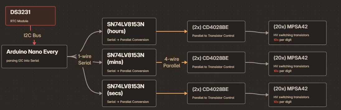
The way this first iteration worked revolved around the Arduino parsing an I2C signal from the DS3231 RTC, and converting it into a serial signal. This serial line was then converted into BCD using the SN74LV8153N.
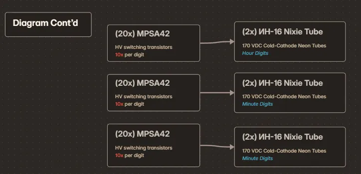
Finally, I used a combination of the CD4028BE (which controlled the transistors based on the BCD signal) and the MPSA42 transistors (for high voltage switching) to drive the nixie tubes using the BCD signal.
Part list:
- Primary Microcontroller: Arduino Nano Every
- Arduino -> Parallel Chips (3 total): SN74LV8153N
- Parallel -> BCD Chips (1 per tube): CD4028BE
- BCD -> Nixie High-Power Transistors (1 per nixie pin): MPSA42
- External RTC Module: ChronoDot
- Nixie Tubes: ИН-16
2nd Iteration (In-Progress):
Objectives:
- Get assembly made into a PCB
- (as an addendum to the above), familiarize myself with KiCad and/or Altium Designer
- Condense design to use less components
Parts Overview:
Logic components:
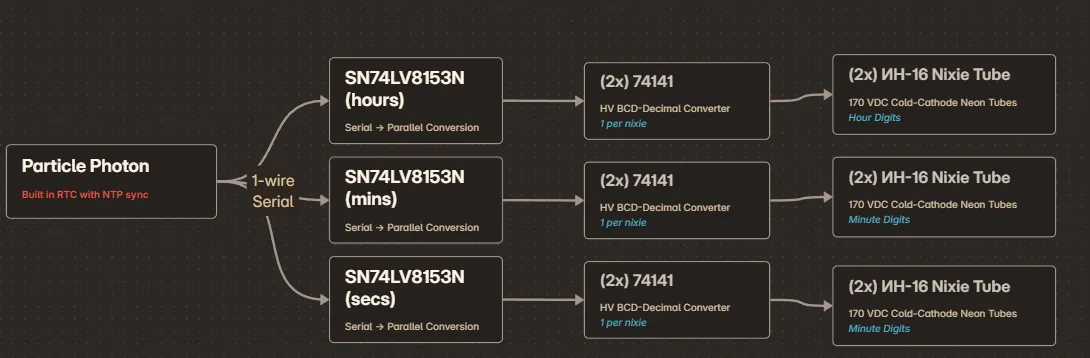
- Primary Microcontroller: Particle Photon (not photon 2)
- MCU -> Parallel Chips (3 total): SN74LV8153N
- Optoisolators (not currently being used): ACPL-844-000E PDIP-16 Optocoupler
- Parallel -> Nixie (1 per tube): Soviet 74141
Nixie Tubes:
- Nixie Tubes: ИН-16
Power components:
- 24V to 5V converter: RS3K-2405DZ_H3
- 24V to HV converter: R24-150B
- HV power adjustment potentiometer: 3296W-1-502LF